La fabricación / The making

Motor Bell Crank
Motor Bell Crank
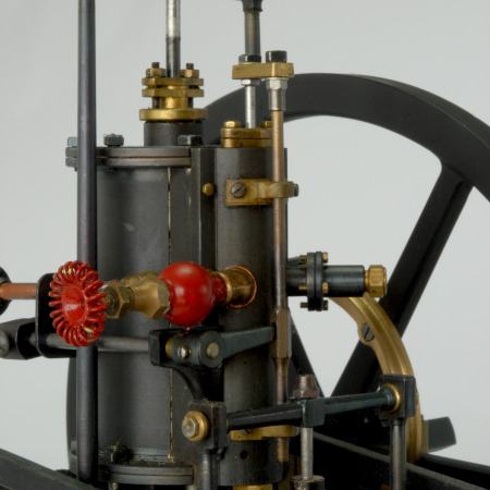
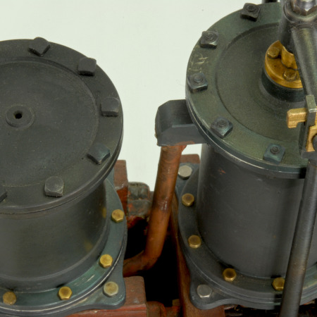
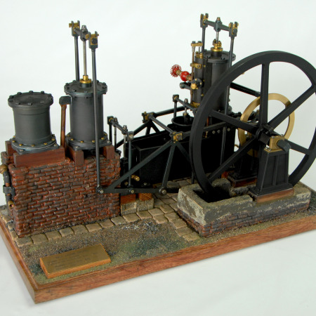
Los primeros motores a vapor eran muy grandes, y requerían de una gran estructura de mampostería, que sostenía el cilindro y la viga oscilante. Pronto se hizo evidente la necesidad de disponer de un motor más pequeño y por ende fácil de ubicar y de trasladar, en caso de necesidad.
Fue William Murdock, un ingenioso mecánico que trabajaba para Boulton & Watt, quien en 1802 diseñó un motor pequeño, integrado, fácil de ubicar en un espacio pequeño.
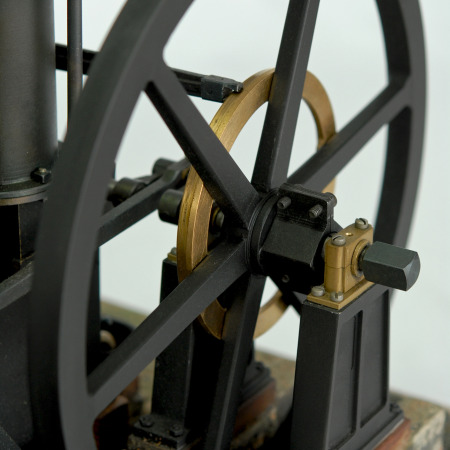
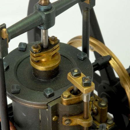
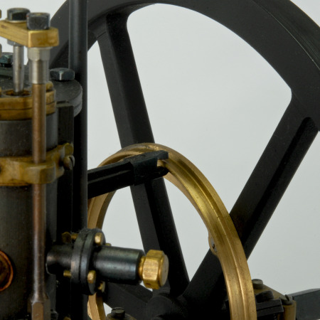
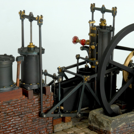
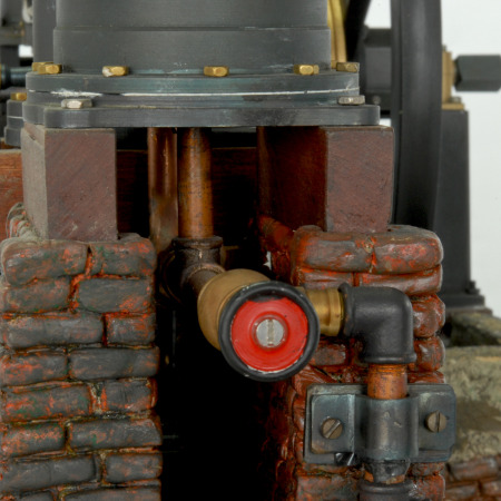
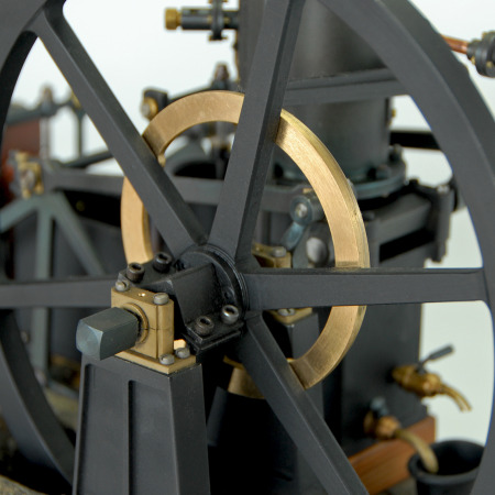
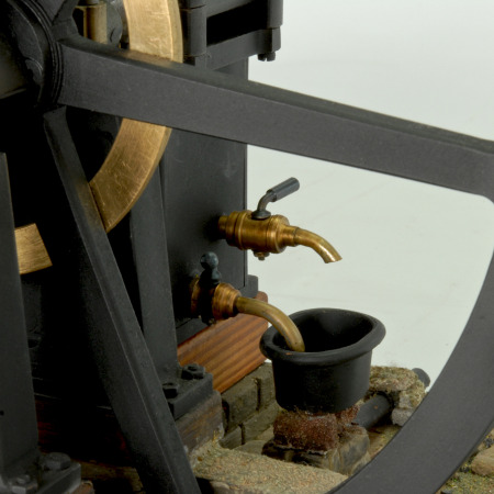
Una cisterna que contenía el condensador servía de base para el cilindro. El distribuidor se accionaba desde un anillo excéntricamente atornillado al volante.
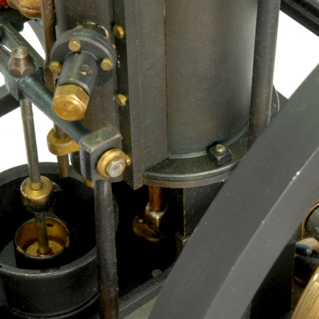
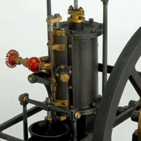
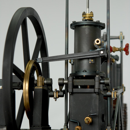
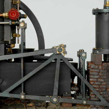
El movimiento alternativo del pistón se transformaba en rotativo mediante tres bielas ubicadas a cada lado del motor: una vertical, una con brazos a noventa grados y una horizontal.
Este recurso para girar noventa grados la dirección del movimiento era similar al utilizado en las mansiones, que podían llamar a la servidumbre desde el salón tirando de un cordón unido a una campanilla remota. Cuando éste debía rodear una esquina se colocaba una pequeña palanca con dos brazos a noventa grados. De aquí el nombre con que se conoce al motor: “Bell Crank Engine” (motor de biela de campanilla).
El motor fue un gran éxito comercial, y Watt & Boulton fabricó y vendió cientos de unidades. En el modelo reproducido la palanca se extiende horizontalmente en ambos sentidos, para accionar un compresor de aire, disposición adoptada en una unidad suministrada en 1802 a una fundición de hierro en Perth.
Bell Crank Engine
The first steam engines were heavy and large, and required a massive masonry structure to hold the cylinder and the oscillating beam. The need for a smaller and more portable engine soon arose.
In 1082, William Murdock, a creative mechanic who worked for Boulton & Watt, designed a small integrated engine , which was easy to place and to move wherever the owner needed it, since it required no heavy structure.
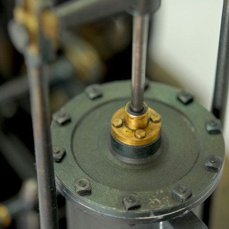
A cistern contained the condenser and was as the basis for the cylinder. The distributor was driven by an eccentric ring bolted to the flywheel and the reciprocation movement of the piston was converted into a rotational one by the use of three connecting rods at each side of the engine: a vertical one, an angled one and one horizontal one.
This resource, used to turn the movement direction ninety degrees, was similar to that of calling the servants in a mansion by hauling a rope attached to a remote bell. In the same way that the rope turned the corner, this engine used a small lever with two arms at right angles to change the direction of the movement. Hence the name of the engine: “Bell Crank”.
The engine was a huge commercial success and Watt & Boulton made and sold hundreds of units.
In the model I built, the lower arm of the bell crank extends in both directions to drive an air compressor. This was a provision adopted in a unit provided in 1802 to an iron foundry in Perth.
Características (features)
Potencia (power)
3 op: 4, 6 u 8 HP
Volante (flywheel)
240 cm (8’) dia.
Carrera (stroke)
60 cm (2’)
Velocidad (speed)
40 rpm
– – –
Modelo (model)
Esc. 1:15
2010
